使用Keil语言的嵌入式C编程教程(下)
2021-05-05 16:29
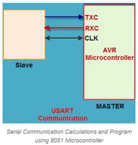
标签:key rup 时延 mic 收信 orm 窗口 任务 图像 使用Keil语言的嵌入式C编程教程(下) 用8051单片机进行定时器/计数器的计算与编程 延迟是应用软件开发中的重要因素之一。然而,在实现定时延迟的过程中,正常的延迟并不能给出克服这一问题的宝贵结果。定时器和计数器是微控制器的硬件组成部分,在许多应用中使用它来提供具有计数的宝贵时间延迟脉冲两个任务都是通过软件技术实现的。 定时器延迟 WAP使用T1M2(timer1和mode2)生成500us延时? #include void main() void delay() { 基于8051单片机的串行通信计算与编程 串行通信通常用于发送和接收信号。8051微控制器包括由Rx和Tx引脚发送和接收的信号的UART串行通信。UART接收字节的数据并按顺序发送各个位。寄存器是一种在存储器中收集和存储数据的方法。UART是一种半双工协议。半双工是指传输和接收数据,但不能同时进行。 1. WAP将字符“S”传输到串行窗口使用9600作为波特率? 28800是8051微控制器的最大波特率 28800/9600=
3 That baud rate ‘3’ is stored in the timers #include void main() { 2. WAP从超级终端接收数据并使用9600波特将数据发送到微控制器的端口0? 28800是8051微控制器的最大波特率 28800/9600=
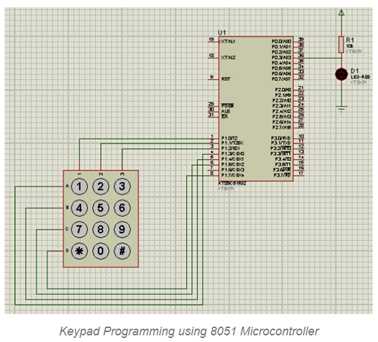
3 That baud rate ‘3’ is stored in the timers #include void main() 用8051单片机中断程序 中断是强制停止当前程序并立即执行其他程序的信号。8051微控制器提供6个内部和外部中断源。当中断发生时,微控制器暂停当前任务并通过执行ISR处理中断,然后微控制器返回到最近的任务。 WAP在定时器0中断时执行左移操作,然后在主功能中执行P0的中断操作? #include unsigned char b; void timer0() interrupt 2 //selected timer0 interrupt// 用8051单片机进行键盘编程 矩阵键盘是一种模拟开关设备,在许多嵌入式应用中使用,允许用户执行必要的任务。矩阵键盘由行和列中矩阵格式的开关排列组成。行和列连接到微控制器,使得开关行连接到一个管脚,并且每列中的开关连接到另一个管脚,然后执行操作。 1. WAP to toggle the LED by pressing the switch #include #include sbit r1=P2^0; void main() r1=0; LED=0xff; 3. WAP to display the number 0,1,2,3,4,5 on the seven segment by
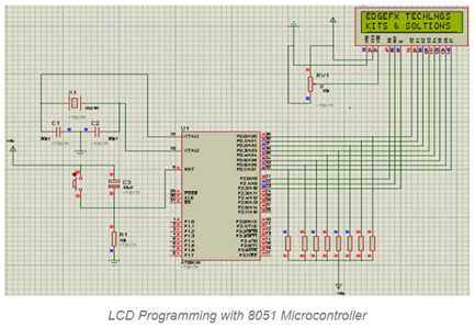
pressing the respective key on the keypad? #include sbit r1=P2^0; sbit c1=P3^0; sbit r2=P2^0; sbit c2=P3^0; sbit a=P0^1; void main() { r1=0; a=1; if(c1==0) { a=0xFC; } If(c2==0) { a=0x60; } if(c3==0) { a=0xDA; } If(c4==0) { a=0xF2; } } 用8051单片机进行液晶显示编程 LCD显示器是一种电子设备,在许多应用中经常用于以文本或图像格式显示信息。液晶显示器是一种可以在屏幕上轻松显示字符的显示器。液晶显示器由8条数据线和3条控制线组成,用于与微控制器接口。 WAP to display the “EDGEFX KITS” on LED display ? #include voidlcd_initi(); sbitrs=P2^0; lcd_initi(); void display(unsigned char *s, unsigned char r) en=1; unsignedint a; 使用Keil语言的嵌入式C编程教程(下) 标签:key rup 时延 mic 收信 orm 窗口 任务 图像 原文地址:https://www.cnblogs.com/wujianming-110117/p/13192102.html
{
unsigned char i;
TMOD=0x20; //set the timer mode//
for(i=0i
{
TL1=0x19; //set the time delay//
TH1=0x00;
TR1=1; //timer oN//
While(TF1==0); //check the flag bit//
TF1=0;
}
TR1=0; //timer off//
}Normal Loop Delay
unsignedint k;
for(k=0;k
}
SCON=0x50; //start the serial communication//
TNOD=0x20; //selected the timer mode//
TH1=3; // load the baud rate//
TR1=1; //Timer ON//
SBUF=’S’; //store the character in the register//
while(TI==0); //check the interrupt register//
TI=0;
TR1=0; //OFF the timer//
while(1); //continuous loop//
}
{
SCON=0x50; //start the serial communication//
TMOD=0x20; //selected the timer mode//
TH1=3; // load the baud rate//
TR1=1; //Timer ON//
PORT0=SBUF; //send the data from SBUF to port0//
while(RI==0); //check the interrupt register//
RI=0;
TR1=0; //OFF the timer//
while(1); //stop the program when character is received//
}
{
b=0x10;
P1=b
}
void main()
{
unsigned char a,i;
IE=0x82 //enable the timer0 interrupt//
TMOD=0x01;
TLo=0xFC; //interrupt timer//
TH1=0xFB;
TR0=1;
a=0x00;
while(1)
{
for(i=0;i
{
a++;
Po=a;
}
}
}
sbit a=P3^0;
sbit b=P3^1;
sbit c=P3^2;
sbit d=P3^3;
void delay();
void main()
{
while(1)
{
a=0;
b=1;
c=1;
d=1;
delay();
a=1;
b=0;
c=1;
d=1;
void delay()
{
unsigned char i;
TMOD=0x20; //set the timer mode//
for(i=0i
{
TL1=0x19; //set the time delay//
TH1=0x00;
TR1=1; //timer oN//
While(TF1==0); //check the flag bit//
TF1=0;
}
TR1=0; //timer off//
}2. WAP to Switch ON the LED by pressing the key ‘1’ on the
keypad?
sbit c1=P3^0;
sbit LED=P0^1;
{
if(c1==0)
{
}
}
#define kam P0
voidlcd_dat(unsigned char );
voidlcd_cmd(unsigned char );
void delay();
void display(unsigned char *s, unsigned char r)
sbitrw=P2^1;
sbit en=P2^2;
void main()
{
lcd_cmd(0x80);
delay(100);
lcd_cmd(0xc0);
display(“edgefx kits”,11);
while(1);
}
{
unsignedint w;
for(w=0;w
lcd_data(s[w]);
}
}
voidlcd_initi()
{
lcd_cmd(0×01);
delay(100);
lcd_cmd(0×38);
delay(100);
lcd_cmd(0×06);
delay(100);
lcd_cmd(0x0c);
delay(100);
}
voidlcd_dat(unsigned char dat)
{
kam = dat;
rs=1;
rw=0;
en=1;
delay(100);
en=0;
}
}
voidlcd_cmd(unsigned char cmd)
{
kam=cmd;
rs=0;
rw=0;
delay(100);
en=0;
}
void delay( unsigned int n)
{
for(a=0;a
上一篇:Java虚拟机-记忆集的疑问